In previous posts I described mounting the motor-transmission assembly and the battery box located where the radiator used to be. Now for the rest of the components. It's a bit of a Tetris puzzle, but the other components that I want to place in the engine compartment include:
- DMOC445 motor controller
- RM4 fluid heater with pump
- DC-DC converter
- Zivan NG3 battery charger
- Vacuum pump and reservoir (for power brakes)
- Accessory battery (standard 12V starter battery, or a smaller version?)
- 2 electrical boxes for relays, shunts, connectors, etc.
Of course, none of them were really designed with the Saturn engine compartment in mind, nor were they designed to nest together well. After hours of head-scratching and experimentation with various placements, we came up with a plan that gets everything placed reasonably well with the exception of the Zivan unit. So it looks like the Zivan will be relegated to the trunk after all. Here's the layout schematically.

The components are mounted to 2 trays that are affixed to various frame members in the engine compartment. It was manufactured in 2 pieces so that they could be easily loaded/unloaded. The main tray will be attached to the passenger side frame (near where the original upper engine mount was located), to the subframe in the center-rear of the engine compartment (just behind the steering rack), and to the angle iron welded in place to support the radiator battery box. This tray will hold the DMOC controller, RM4 fluid heater, the vacuum system reservoir, and the 12V electrical box. A second tray bolts to the main tray in 2 locations (front and rear of the engine compartment) and to the driver side frame (near the transmission torque rod mount). This tray will hold the DC-DC converter, vacuum pump, a U1 accessory battery (wheelchair battery), and the high-voltage electrical box. It was possible to rearrange the components so that a standard Saturn starter battery would fit, but why carry the extra weight when I won't need to start anything?!? The U1 size should be plenty big to act as a capacitor between the DC-DC converter and the various 12V loads in the car.
Here's the main tray installed.
This is a close-up of the rear extension, showing the tray attached to the subframe behind the steering rack.
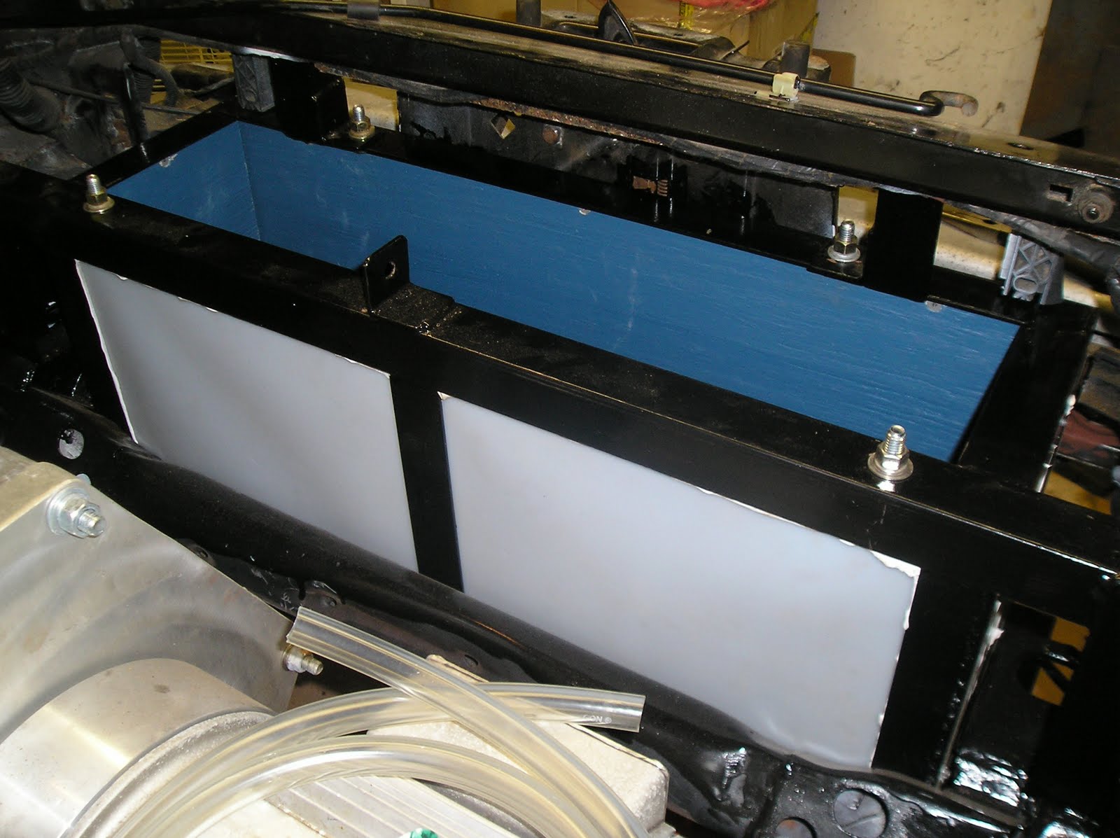
Here's a close-up of the attachment to the radiator battery box rear support.
Here's a view of the second tray installed. Notice that the bell housing sticks up above the tray, complicating placement of some of the components. This tray is bolted to the main tray on the left and screwed (self-tapping screws) into the main car frame member on the right.
I don't have a good photo showing the trays installed with components in place. I'll update with good photos once everything is mounted in place.
Most of the components are simply bolted through the angle iron bottom of the two trays, often with rubber mounts, but the fluid heater and vacuum pump were extra challenging.
The fluid heater doesn't have any straight edges. It looks a bit like two tapered cups joined together at their rims. There is a flange which runs along the axis of the heater with 2 holes drilled into it that is meant to be used to mount the unit. This flange does not look beefy enough to me, and I was worried that it would not hold its own weight considering the vibrations and g-forces of a driving car, so I opted to use a "riser" pipe clamp (
McMaster-Carr PN3065T54) around the lower tapered surface. The riser clamp bolts were welded to two pieces of angle welded vertically to the bottom of the tray. By the way, McMaster-Carr has without a doubt THE best website in the world. I am continually amazed at how easily I can search for items, and how easy it is to order things. Plus they've delivered to me the next day every time, without fail. They rock!
Anyway, here's a picture of the fluid heater with the rise clamp. You can barely see the "mounting flange" on the left side of the unit.
The idea is to bolt the riser clamp to little uprights welded into the main tray in the back left corner (looking at it from in front of the car). In order to keep it from hitting the hood, the bottom of the heater will actually descend below the tray by a few inches. It fits nicely just behind the motor casing but still above the drive shaft. It might be hard to see here (kinda dark - I need some photography lessons), but this picture shows the heater installed in the tray. You can see one of the angle iron pieces to which the riser clamp is bolted.
The vacuum pump also presented some challenges. Not because it is difficult to mount, but it's just awfully big, and I wanted to keep it close to the brake booster. I ended up actually mounting it vertically, next to the brake booster and master cylinder, with the business end up. I'm not totally enamored of the location, but hopefully it will work ok for now. I
think it will clear the hood, but I haven't tried it yet. My eyeball says it's going to be close. I don't have a great picture of this yet, but I'll take lots of pictures once all the components are installed. The vacuum reservoir is going to hang down from the main tray to the right of the fluid heater between the motor casting and the firewall. There's room there, and I plan to just use 4" pipe clamps attached to the back of the tray.
Here's a picture of the DC-DC converter and accessory battery approximately in place. This also shows the approximate location of the high-voltage electrical box. Again, the lighting leaves a lot to be desired.
Next step: drill mounting holes in the trays, paint them up, and install them.