Rubber or solid mounts?
Most EV converters use the rubber engine and transmission mounts. Since I won't have to deal with the vibrations of an ICE and since the AC24LS doesn't have the torque of the ICE, I've decided to mount the motor-transmission solid to the frame. If something bad happens, or the drivetrain sounds bad, I should be able to convert it back to the rubber mounts.
Motor mount
Since the motor orientation is such that the mounting face is in the down position, it would be unwieldy to use the upper engine mount. Instead, the plan was to mount the motor to the engine cradle, in approximately the same location as the original lower engine mount. The design of that mount was done in a step-wise fashion.
Step 1: Attach angle-iron brackets to the motor mounting grooves. Basically, cut 12" pieces of angle (1.5" x 1.5" x .125" thick) and drill a couple of .407" holes (clearance for the M10 bolts which fit in the grooves) in each one. Once attached to the motor it looked like this.
Step 3: Bolt a short piece of angle to the cradle and tack weld the assembly made in Step 2. As you can see, the cradle is not level at all but it doesn't matter using the method employed here.
Step 4: I am so fortunate to have a friend with a welder. The next step is to remove the bracket and weld everything together solid. Yes, that's right. We're using an old hollow-core door with a galvanized plate bolted to it as a welding table. Nothing is too good for this project!
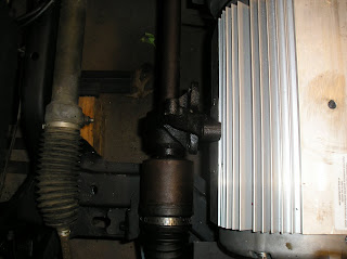
Step 5: Build a bracket for the passenger-side driveshaft (this long shaft is in two sections so that the CV joints are in the same location for both wheels). It's amazing what can be built with pieces of angle and flat bar. Here's a picture of the location of the driveshaft support (sorry it's a little dark - that's the steering rack to the left).
Here's a picture of the finished bracket, nicely painted. The two bolts pointing at the camera are spaced to mate up with two holes in the driveshaft support.
Next... installation of the motor mount, and the transmission mounts.


No comments:
Post a Comment