Tuesday, August 10, 2010

Low voltage wiring (engine compartment)

Now that the Primary AC Interlock Relay has been installed and the wires have been run up to the engine compartment, I can start wiring the engine compartment relays.  The EA kit that I purchased includes detailed instructions on how to make all the electrical connections necessary.  The instructions are a little out of date, unfortunately, so they don't exactly match the components that came with the kit.  For instance, the DC/DC converter supplied with the kit (Elcon ####) doesn't need the input voltage filter that is specified in the intstructions (originally for PFC DC/DC converter).  In addition, I added a "DMOC Kill Switch" within reach of the driver, necessitating an additional "DMOC Relay" wired to that switch.  So I adapted the electrical schematic provided to depict these changes, as well as adding details as to where I'm pulling power from the existing 12V system and locations of the various components.

I'm working on being able to load the electrical schematics to the blog, but in the meantime here are some images of the wiring as it was being completed.  First, a view of the passenger side of the engine compartment.

This electrical enclosure in the middle of the picture contains:
-Secondary AC Interlock Relay
-Key Switch Relay
-Neutral Switch Relay
-Regen Relay
-DMOC Relay
-Vacuum Pump Relay

To the right of the enclosure is the DMOC controller.  Directly behind the enclosure is the water heater.  Barely visible in the upper right corner is the brass tee at the top of the vacuum pump.  There are wires in the red corrugated wire-minder running from the enclosure to both the heater and vacuum systems.

On the driver side of the engine compartment is another electrical enclosure which houses 3 shunts for measuring current.  The large shunt in the center measures the current going to the motor controller.  The 2 smaller ones measure the current being supplied to the water heater and accessory battery.  This picture shows the enclosure with all the wiring except the big battery cables.

The new accessory battery (lawn tractor size U1, since I won't need the "cranking capacity" of the original battery) resides next to the "shunt" enclosure.  This picture shows the wiring coming into the battery (Ground not connected! - I'm scared to connect it right now...).  The "bundle" of white wires attached to the chassis next to the junction box are the ground lines from the relay box, the DMOC controller, the vacuum pump, and the transmission.  The thick black wire (#4 awg - I know, overkill, but it had the right size ring lugs) connects the chassis to the battery ground.
Notice the coil of many-colored wires nestled next to the junction box?  That's what's left of the original engine wiring harness.  I conscripted 2 of the wires as "keyed 12V" lines for the various relays/DMOC/Vacuum, so the rest are unused in this conversion.  However, rather than trying to dismantle and remove the wires individually I electrically isolated the ends/connectors and left them in the car.  Never know when I might need to commandeer another of the old circuits!  Here's the wire bundle before I coiled it up.  Ugly!  And a lot of it covered with oil....
Finally, to round out the 12V wiring, the last component to be installed is the potbox which converts the accelerator pedal position (not the "gas" pedal - tee, hee) into a resistance which the DMOC controller can interpret as a throttle request.  In the ICE, pressing the pedal pulled a cable through a sleeve which controlled how much air was sucked into the intake manifold.  The end of the cable was held in place by a bracket which positioned the cable properly.  In the EV, I needed to duplicate that positioning in relation to the potbox.  My solution was to put it in an electrical enclosure with the potbox mounted in such a way that the side of the box acted as the positioning bracket.  Also, an additional return spring was attached to the potbox arm from the opposite side of the box as a redundant feature.  Don't want the potbox throttle stuck in the "on" position!

A small metal rod is attached to the end of the accelerator cable, forming a "T".  The rod nicely fits through the pre-drilled holes in the potbox arm (coincidence?  I think not.).  I needed to come up with a way to keep it in there, though, and I forgot to look at the original installation to get ideas.  I found a small aluminum piece (from a toy Erector set) that was the right width and had slightly-too-small holes drilled in it at about the same pitch.  What luck!  So I opened one of the holes up so that it could hold the other side of the "T" and bolted it to the potbox arm.  Here's a side view:
Here's the top view, with the potbox mounted in the box.  The supplemental return spring is connected to a "spring connector stud" I found on McMaster-Carr (what a great place that is!).
Because of the length of the accelerator cable and because I was limited in where I could mount this box, I had to mount it on the relay enclosure at a bit of an angle.  Once the lid is on and everything is buttoned up, it doesn't look half bad.  At the moment it is only attached to the lid of the relay box, which may or may not hold up over time from the jolts of driving, but I can always reinforce it with steel later.

Friday, July 23, 2010

Low voltage wiring (trunk area)

The Primary AC Interlock Relay (PACIR) is supposed to be located near the battery charger, which is supposed to be near where the AC plug will reside in the car (to minimize the amount of AC wiring in the car, I suppose).  I'll be following most of the conversions and put the AC receptacle where the gas cap used to be.  Since I couldn't find a spot for the charger in the engine compartment anyway, it all works out to the good.  I found a "surplus" electrical box in the trash at work, so I liberated it to mount in the trunk area of the car to hold the PACIR and the AC power distribution terminal blocks.  I found it convenient to hang it from the back of the main battery box.

The PACIR is energized when the car is plugged in, so it's simple enough to connect the two hot leads from the 220VAC input.  Like so.

The "outputs" from the relay need to run up to the engine compartment to connect to the Secondary AC Interlock Relay and the Key Switch Relay, so I needed to run 4 wires from the PACIR to the engine compartment.  I ran 3 additional wires with these 4 which will eventually connect to the batteries in the radiator battery box for the PakTrakr.  But how to run these 7 wires?  Although I suppose I could have run them along the inside of the passenger compartment and then through the firewall, I chose to pop a hole in the trunk and run them along the underside of the car.  There was a very convenient location right next to the charger to do this.  I couldn't find a convenient location to pop through the firewall without dismantling the dashboard.  Not something I am itching to do at the moment.

Here's the hole with a bulkhead fitting stuck through it.  I used a little piece of silicone rubber to seal around the fitting.

Here's the rear electrical box with the relay wired.  The wires that are just hanging there will be for the PakTrakr.

The 7 wires running along the underside of the car are placed inside a split corrugated sleeve and fed through the clips that were originally used to hold the fuel line.  How convenient!

Monday, July 12, 2010

Main battery racks installed

Trying to catch up with some entries.  I hope I remember what I did a month ago!

Installing the main battery racks:
Before loading them in, I reinstalled the trim panels and the carpeting since I figured it would be really hard to do that after the racks are in place.  Of course I then found out that the trim panel interferes with the box.  So I had to cut a slot in the trim panel on each side near the rear seatbelt anchors.
Here are the main racks in place with the wood bottoms installed.
There are 10 bolts (either 3/8 or M14) attaching the racks to the car frame.  Here are images of a couple of those.  The first picture is looking at the front of the rack where it is attached to the floor of the car where the rear passengers' feet used to be.  The second picture shows the back of the rack where it is attached to the trunk floor just ahead of the spare tire well.  In both cases the floor sheet metal is sandwiched between two 1/8" steel plates.
Now that the racks are in their final resting position, I could finalize the location of the conduit that will carry the main battery cables from these racks to the motor controller and front battery rack.  Here's a picture which shows the caulked opening. The outlet to the junction box located in the hump is seen poking through.  A piece of flex conduit will attach to that and run up to an elbow which will enter the battery box at the level of the top of the batteries.

Before I can assemble the boxes and put the batteries in, though, I need to get the car back on its wheels.  I am worried about the car sitting on jack stands with all that weight!

Things to do before the wheels go on:
  • Run the 12V and PakTrakr wires from the engine compartment to the trunk.
  • Run the charger wires and #2 battery cables from the rear battery box to the engine compartment (through the PVC conduit).
  • Run the wires from the engine compartment to the dashboard (gauge wires, Regen box wires, heater control wires).
  • Re-assemble fender skirts and front bumper.
  • Complete 12V and signal wiring in engine compartment.

Monday, June 14, 2010

I haven't updated this in a while, I guess.  Again.  Been busy.  Again.  I had to take a few weeks off from working on the car for my daughter's high school graduation, my son's confirmation, and getting the house ready for the inevitable blow-out party.  Then, I've had a series of setbacks trying to install components in the engine compartment.  But I may have made some progress this weekend, and I have a little time to write an update.

Vacuum System for Power Brakes:
My plan was to put the vacuum reservoir behind and under the DMOC, and above the drive axle.  Like this (see the black pipe bomb {kidding!} next to the motor?).

However, I forgot that the DMOC is mounted on rubber bushings and my original bracket for the reservoir interfered with that.  So I had to extend the bracket a bit so the reservoir hangs a little lower.  It still clears the driveaxle but I'm not sure about the steering.  We'll see.  Here's a picture of the reservoir with the little extenders on the pipe clamps.

As for the vacuum pump, I came up with a kind of wacky place to put it.  I hope I don't pay for this later.  As far as I could research the pump will work in any orientation, so I put it upright next to the brake booster.  Here's the pump installed (boy, it sure is hard to see black on black, isn't it?).

Water Heater for Cabin Climate Control:
Just above the vacuum system is the water heater.  There's not much space around the heater core fittings, so I had to be a little creative with heater hose.  I bought a couple of molded hoses with hard 90 degree bends and cut them to make the tough initial bend coming out of the heater core.  Once those bends were made, it was pretty easy to plumb into the heater, changing the return line from 5/8" to 3/4".

 Heater core fittings:

Hoses running from heater to heater core:

Next, can it be that I'm finally ready to install the main battery boxes???

Wednesday, May 19, 2010

Passenger Door Window

In my last post, I showed that the rear sash bushing in the window regulator was missing.  I had thought about machining a replacement bushing in Delrin, but in the end decided it wasn't worth it.  Instead of spending hours machining something that may or may not work I decided to just get a new regulator.  I am anxious to get this car on the road and spending time on non-EV-related activities just doesn't seem worth it to me.  So I found junkie regulators for $50 (plus shipping, because none of the boneyards near me have Saturn coupes), or brand-spanking-new regulators from RockAuto.com for $80 plus or minus.  No brainer for me - a few clicks of the mouse and 2 days later a brand-new regulator shows up at my door.  Nice!

I don't have any pictures of the intermediate steps, but suffice it to say that the new regulator went in pretty easily.  However, when I tried to put the glass back in it didn't seem to want to go in straight.  And once I was able to wiggle it into what I thought was the right spot it seemed jammed.  Thinking that there might be some debris in the window track, I started feeling around inside and discovered that the rubber guide at the front window track was twisted which prevented the window from sliding properly.  Aha!  So that's why the bushing broke in the first place!

Well, I couldn't access that rubber piece from the inside of the door so I had to take the outer (plastic) panel off to access it.  It actually was fairly easy to do - remove 3 nuts and the side-view mirror comes off, pry out the outer window trim, undo 10 torx bolts, and voila! the panel falls off.  Once the outer panel was off it was easy to readjust the rubber guide - here are a couple of pics of it already fixed (forgot to take a picture of its original state!).

With the exterior panel off, installing the window was a breeze.  I checked the operation of the window a few times (works beautifully) and then reassembled the door.  Of course I forgot to install one of the styrofoam pieces (doh!), so I had to take it apart and put it together again, but it's amazing how easy it is to do something for the second time.

A couple of pics of the newly assembled and perfectly operating door.  Success!

Yah, I know.  The car is filthy.  All in good time.........

Now, if only the EV parts of the car can go together as easily.

Wednesday, May 12, 2010

Radiator Battery Box and Passenger Door Window

Between throwing out my back and having a house full of relatives not much has been happening, but I made some small progress this week.

Radiator Battery Box
I previously showed the car modifications needed in order to put two batteries where the radiator used to reside.  Since then I've:
  • Painted the frames
  • Cut pieces of wood which will be the bottom and sides of the box
  • Painted the wood with (blue) epoxy paint
  • Cut pieces of plastic (HDPE, 0.020" thick) to put in between the wood and frame (prevents water which might come in through the grille from soaking into the wood)
  • Attached the wood and plastic (with caulking to seal between plastic and frame) to the frame with self-tapping screws
  • Cut off the excess screw length
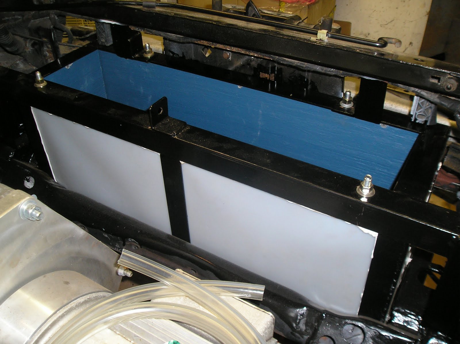
Here's a picture of the frame with wood/plastic/caulk, ready to be installed in the car.

Here are a couple of views of the box installed:
Looking into the engine compartment toward the front of the car.
Close-up of the front corner of the box, looking through the space where the headlights will reside.
View from the front of the car.  It's really hard to see, but the sway bar is lower than the bottom of the box, so it shouldn't interfere with the operation of the car (or the belly pan I'd like to install).

Passenger Door
When I bought the car the passenger door window mechanism was broken.  When I took the door apart to investigate I saw that one of the bushings that connects the scissor mechanism to the window sash was missing.  Here is a picture of the sash and scissor mechanism showing where the part is missing.

There are two of these bushings.  Here's a picture of the front bushing.

You can't purchase those bushings individually, unfortunately, only as part of the entire regulator (sash, scissor mechanism, motor), so I'm going to try and machine a new bushing out of delrin.  If that fails, then I'll get a junkyard regulator to replace the entire thing.

Tuesday, May 4, 2010

Battery Boxes (again)

In previous posts, I showed the design and fabrication of the metal and wood portions of the battery boxes.  My original intent was to have the lids push down on the batteries with small lengths of PVC pipe.  I've seen this done on several conversions on the web.  The main advantage of this method for me is that it simplifies the bottom of the box, especially how easy it will be to contain any spills.  However, it greatly complicated the design and strength requirements for the lid.  My original plan called for an angle iron frame and support members that would be very heavy and would require large bolts to hold it in place.  These large bolts and heavy lid would have to be removed every time I wanted to check water levels or electrical connections.  In addition, because of the placement of the battery boxes in the back of the car, it would be very awkward to reach some of the bolts.  Finally, it was not clear to me that the lids could be removed with the seats in place.  Too much effort!

So, instead, I opted for a different design.  This one is also described by many converters on the web.  Instead of pushing down on the batteries from the lid, I will use threaded rods with steel pieces laid across the tops of the batteries to pull them down from the base of the box, just like the starter battery in all ICE cars.  I opted for 5/16" threaded rod and 1" steel box tubing in place of the usual M4(?) threaded rod and polypropylene battery straps or molded pieces that are used for starter batteries.

Since there is little space underneath the battery boxes (I'm trying to keep the batteries as low as possible without cutting into the floor) I welded nuts to the top side of the bottom frame.

The steel tubing was a little challenging. For the main box (6 batteries side by side) there was plenty of room for the tubing to run down the center of the batteries.  There is a nice gap in the row of filler caps, and plenty far away from all of the battery terminals.
However, because the box was designed to just barely fit the width of the back seat area, the top frame angle pieces point "in."  This means that the threaded rod will be directly under a piece of steel, and so the tubing cannot be dropped straight down on it.  So I cut slots in the tubing so that it can be slid onto the threaded rod from the side.
Also, because the tubing will have to span 6 batteries I wanted to add a threaded rod to the center of the box to limit the span.  So, I made a "T" out of a couple pieces of flat bar and welded a nut to that for the center threaded rod.  This meant that I had to cut the bottom wood piece in half (so now it's much easier to load into the box!) to make room for the new "T."

Since there are three tie-down places for this piece of tubing, I put the two slots on opposite sides.  So, when installing the tubing I drop the tubing over the center threaded rod with the tubing pointing to the corners of the battery box, then rotate the tubing until the ends meet the two threaded rods at the ends of the battery box.
Here's a picture showing the end of the steel tubing.  It's hard to tell from this angle, but there isn't a lot of space between the top of the threaded rod and the steel angle.

For the rearmost battery box the steel tubing was challenging in another way.  In this case the top frame is angled "outboard" so there will be no issues with dropping the tubing straight down onto the threaded rod.  However, in this box the batteries are laid end-to-end, and what I quickly discovered is that there is not room for the steel tubing between the battery terminals and the filler caps.  Instead of opting for a smaller version of tubing (1/2" would probably work ok) for each row (there are 2), I chose to hold the batteries down by their edges instead.  My plan is to have a single piece of tubing run along the common edge between the two rows of batteries, with "outriggers" welded in place to help keep the batteries from jostling out of place.  Kind of looks like a TV antenna?

This welded tube structure will be held down in two locations, inboard from the very end of the box, so the span is not excessive.  In these locations, there's a nice strong piece of angle to weld the nuts to.
In both cases, the batteries will be constrained at the bottom so they cannot slide around.  No pictures yet, but I plan to use pieces of wood screwed into the bottom.

The radiator box added another challenge to the hold-down scheme.  The batteries are also laid end-to-end in this box, so the 1" tubing will not fit.  So I bought some 3/4" aluminum tubing to lay across the batteries.  However, this box is not as tall as the rear battery boxes (by mistake?  Possibly.) so I've opted in this case to use my original intent of pushing the batteries down.  These batteries will be loaded from the bottom so I will lay pieces of 1" tubing across the battery (side-to-side) which will contact the top frame when they are in place.  I may have to add a piece of silicone rubber under these pieces of tubing so that the batteries are held snugly when the base is fully installed.  A junk piece of steel tubing (welding practice!) illustrates the concept.

So, after slapping some paint on the newly-welded parts of these boxes I should finally be able to load them into the car!