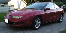
Saturday, January 30, 2010

Building the wood battery boxes

I previously showed the main battery racks (metal frames) being made and mounted in the back seat.  Since then I've wire-brushed the surface rust off and primed and painted them with Rustoleum.  The next step is to fabricate the wood pieces that will form the box that will keep prying fingers from high voltage connections and passengers from breathing battery fumes.

I chose to use 3/4" plywood for the base of each box to minimize flex from the battery weight.  Actually, I really splurged and bought oak plywood.  Nice and flat.  For the sides I'm using 1/2" pine plywood.  I'm relying on the steel angle framework to keep the batteries contained in the event of an accident, so the strength of the wood sides isn't really important.
Here's a view of the two main boxes with the wood pieces set in place.
Next steps: paint the wood with epoxy paint and install them using self-tapping screws through the steel angle.

Upper transmission mount

A little catch-up.  I've been too busy to update the blog for a while, but things have been happening!

Since we decided to mount the motor-transmission directly to the frame (no rubber mounts) both of the transmission mounts had to be remade.  I showed the lower transmission mount in an entry back in September(!), but we hadn't finalized the upper transmission mount design way back then.  It's done now and installed.  Here's the design as it looked on the computer.
The piece of angle with 2 holes in it mates up with the transmission, and the single hole on the vertical piece mates up with the mounting hole in the frame.  Simple.  Here's the final piece, painted and in place.
The drive train is now complete.

Monday, January 11, 2010

The Front Battery Rack

Though the main (rear) battery boxes haven't been mounted yet, we decided to work on the front battery box first.  This box is a bit trickier than the rear boxes.  The idea is to put 2 batteries where the radiator used to reside.  Two batteries will fit in there but the problem is how to design it so that the batteries can be accessed (for watering) and so that you install and remove the batteries without disassembling half the car.  Oh, and hopefully the batteries won't be so low that I would forever be worried about hitting the curb when I pull into a parking spot.

Option 1:  Remove the sub-frame member that was originally between the engine and the radiator and put the box there.  With this piece removed the battery box will easily fit in front of the electric motor and clear the upper support in the front of the engine compartment (where the hood latch resides).  Upside: batteries can be dropped in from the top and access for watering will be easy.  Downside: requires serious changes to the car's frame.
The pic below shows where the battery box would reside with this option (each cardboard box represents a battery). The cardboard boxes are higher than the hood-line because they are sitting on the sub-frame that would be removed.


Option 2:  Put the box further forward (under the front upper support).  Since we're further forward the batteries will have to be loaded into the box from the bottom.  Upside: no changes to frame required.  Downside: battery box will have to be very low because of the geometry of the hood latch.

Option 3:  With a few minor modifications to the headlight and hood latch brackets and by trimming (but not removing) the sub-frame member in a few places, the box could be brought back slightly toward the motor and raised several inches.  This seemed a good compromise.

The modifications required are:
1.  Remove the raised portion of the stamping for the hood latch.
2.  Trim the sub-frame in two spots to accommodate the rectangular battery box.


3.  Remove a portion of the headlamp mounting bracket.  Sounds scary, but the parts of the bracket where the headlamp is bolted will remain.  It's pretty sturdy, and all the aiming functionality for the headlamp will still work.  (picture shown further down in this entry)


So, how to attach the box to the car?  There are very few flat surfaces in the engine compartment but after scratching our heads for a while we came up with a plan.  We decided to weld 3 brackets in place to which the battery box will be hung from.  A cross-brace running all the way across the engine compartment that will match up with the upper rear edge of the box, and two smaller brackets that will match up with the upper front edge of the box.
Here's the cross-brace, welded to vertical surfaces on either side of the engine compartment.
 
Here's a pic of one of the brackets for the front upper edge.  Here we used the vertical part of the front support.  I also show here the other modifications to the existing car parts required to make the box fit.

Here's a view with the box bolted in place.  Solid!

Ready to clean up and paint!

Tuesday, December 29, 2009

Batteries!

Even though I'm not quite ready for them, I decided to go ahead and purchase the traction batteries.  It was a convenient time for me to get them (since I could borrow a friend's truck) and the battery distributor (Northeast Battery) gave me a nice price.  I bought 13 Trojan T-1275 Plus batteries with the low-profile universal terminal to provide the minimum 156 V recommended to power my AC-24LS motor.  The universal terminal is supposedly less inclined to loosen with vibration and over time and is the connection I've seen recommended the most by EV converter experts.  This image is from Trojan's product spec sheet for their "plus" line of batteries.


Funny thing happened, though, when I went to pick the batteries up.  I thought the left rear tire looked a little low when I got out at Northeast Battery's parking lot but didn't think too much about it.  Well, when they lowered the pallet of batteries onto the truck-bed I couldn't believe how much the back end dropped!  I looked at the left rear tire again and it was obvious now (with the weight added to the back end) that the tire was basically flat.  It didn't look like the front tires were in danger of losing traction because of the imbalance, but it didn't look that healthy, either.  Yikes!  So I limped to the nearest gas station (less than 1/4 mile away, fortunately) and filled up the rear tires.  Man, I was sitting there for a long time filling that left tire - I topped off the other one, too, while I was at it.  The truck was much more level now, and I felt much more comfortable driving it with the load.  So no worries getting back to my home town (just under a 50 mile drive).  The truck actually rode a lot nicer with the load in back, though I was careful to leave plenty of space in front of me for braking, and was ginger going around curves.

Here's the happy picture of the batteries in the back of the truck.

Even with the tires properly inflated, the back end of the truck was lower than I expected.  By my calculations there was a shade under 1100 lbs sitting there, which caused the back end to drop 3 inches.  It's a bit hard to see with the pictures below (I'm a horrible photographer) but these are loaded and unloaded pictures of the bed height.

Loaded.  (Don't ask me why I placed the yardstick upside down like that)  We're at 19 inches here.

Unloaded. We're at 16 inches here, 3 inches higher off the ground now.

With the help of a strong-backed friend, the batteries are now sitting on the pallet in the basement, waiting for me to get off my butt and finish the battery racks.

Tuesday, December 22, 2009

Battery layout and rack designs Pt 2

The rear battery boxes will be made with 1.5"x1.5"x.125"thk steel angle, welded into 2 boxes which will be bolted together and bolted to the car, either through the floor pan or directly to the frame.


To make sure they will actually fit in the car, we built the boxes in stages.  First, the base of the "lower" rear rack (the one that will hold 6 batteries side-by-side) was tacked together and placed in the car.


Hooray.  It fits.  As you can see by the second image, the left-to-right level is a bit off, but that's because we haven't yet set up the brackets that will anchor the rack in place.  As you can see below, we should be able to utilize the seat belt anchor to secure the rear corners of this box. (Hard to see in this image, but it's the rust-colored spot inside the red circle)


So, since things are looking ok at this point we proceeded to complete the frames.  Here's the lower rack tacked together.  The gap in one of the upper edges is where the opening to the upper box will be.

Here's the upper rack partially tacked together.  It's a more complicated design because it will contain 2 rows of batteries (1 row with 3 batteries end-to-end, 1 with 2 batteries end-to-end).

Here's the upper rack basically finished.

The next step is to put the racks in the car and fit brackets to them to secure them to the car and keep them level.  Our initial plan was bolt the two racks together in place, then bolt the racks to the car in 7 places: the front of the lower rack will be secured to the floor pan on either side of the "center hump" (the floor pan will be sandwiched between two 1/8" thick plates), the back corners of the lower rack will be secured to the seat belt anchors, the rear of the upper rack will be secured through the trunk floor, and the upper rack will be secured through the trunk floor near the rear wheel wells.  Here's a picture showing the lower rack.  You can see where the pedestal supports will sit on the floor.

This view shows where the upper rack will be attached to the trunk floor.

More to come.


Sunday, November 15, 2009

Battery layout and rack designs

It's been almost 2 months since I wrote an update. Obviously I'm horrid in finding time to write. Maybe I'm embarrassed too because, although some progress has been made, compared to most other EV converters I am moving at less then a snail's pace.

In the last post I described the transmission and motor mounts, but I hadn't quite finished the torque rod for the upper transmission mount. Well, it's still not done!  The steel pieces for that have been cut but it is still waiting to be welded together.

Yet, since the motor and transmission are in place I can at least figure out how many of my jumbo batteries will fit in the engine compartment.  I had hoped for 4 and planned on 3, but more careful measurements showed that only 2 will fit. Just barely. And I might have to seriously modify the sub-frame to make it happen. Very disappointing. So that means 11 batteries have to fit in the back seat area. That put me in a bind with the back seat battery box design but I was able to cram them in. Here are a couple CAD views of the back seat area.

 
The "lower tier" (which holds 6 batteries) sits where the back seat bottom was, the "upper tier" will be bolted to the lower tier box and is at the level of the trunk floor. The upper tier box is higher than I'd like, but I really didn't want to cut away any of the floor pan. In addition to the two tiers being bolted together, they will also be bolted to the frame and through the floor pan in 7 places. Should keep them in place in case of an accident.

What is my weight distribution going to be now?
I didn't weigh the car before I started the conversion, but according to the door jamb the car started out with 1470lbs on the front axle and 900lbs on the rear axle. That's a 62%/38% ratio, 2370lbs total. Based on the current battery layout (2 where radiator had been, 11 in the back seat/trunk area) I will have 1570lbs on the front axle and a whopping 1600lbs on the rear axle. That's a 49%/51% ratio. More balanced for handling, you might say, but it will certainly be a lead sled coming in at a svelte 3200lbs. I've ordered custom springs (Springworks) for the rear struts to help accommodate the extra 700-800 lbs on that axle. May have to beef up other components, too. Time will tell.

Wednesday, September 23, 2009

Mounting the motor-transmission assy, Part 2

Completing the motor-mount and installing it took a lot longer than I expected. More than 4 hours last night, but it's done and it seems to work. The culprit was the bracket to hold the driveshaft support. Here's a picture of the mount as of 2 days ago.

The two studs pointing toward the camera were supposed to mate with the driveshaft support bracket. In order to make it easier to attach the bracket we welded the bolts to this mount. Unfortunately, with the driveshaft installed there wasn't enough clearance to swing the bracket into place. So, I had to grind off the bolts. Even with loose bolts, there was still not enough clearance. Besides with loose bolts it was going to be difficult to align the driveshaft properly.

That left only one other option: weld nuts in place on the motor mount. This will allow the bracket to be swung in place and still align the bracket properly. So, we installed the mount onto the motor, pushed the driveshaft into the transmission, and attached the driveshaft support using some short bolts (3/8" x 1" long).

Two problems arose:
1) Somehow the entire driveshaft/mount assembly needs to be taken off the motor so the nuts can be welded in place.
2) The driveshaft support bracket, even though it looks beefy enough, actually flexes quite a bit when lateral force is applied.

For #1, our first thought was to slide the bracket off the mounting grooves on the motor, which will also pull the driveshaft out of the transmission at the same time. That didn't pan out - the bolt heads are so snug in the grooves that they don't really slide. So we ended up disconnecting the transmission from the motor (again) to free the driveshaft. Once they were separated, we could take the mount off with the driveshaft attached.

To solve #2, we added a gusset to the bracket. The freshly painted part of the mount in this picture is the gusset. You can see the newly-welded nuts on there, too.

Here are a couple of pictures of the finished mount and motor installed, with driveshafts intact. Finally!


As you can see by these pictures, the driveshaft bracket can actually be attached in 3 places. We chose to ignore the top one and are only using the middle 2. That top bolt hole was actually in a different plane than the middle 2, so it had to be ground away so that it wouldn't interfere with the motor.

Lower Transmission Mount
This was quite simple. A block of aluminum with two tabbed bolt holes in the top which mate up with the transmission and a single bolt through the center pointing straight down which locates the mount through a hole in the cradle. This is a picture of it before the driveshaft was reinstalled.


Upper Transmission Mount
This is the main torque rod for the transmission. Not yet finished, the plan is to use a piece of angle, some bar stock, and a couple of spacers. More on that later.