Tuesday, December 29, 2009

Batteries!

Even though I'm not quite ready for them, I decided to go ahead and purchase the traction batteries.  It was a convenient time for me to get them (since I could borrow a friend's truck) and the battery distributor (Northeast Battery) gave me a nice price.  I bought 13 Trojan T-1275 Plus batteries with the low-profile universal terminal to provide the minimum 156 V recommended to power my AC-24LS motor.  The universal terminal is supposedly less inclined to loosen with vibration and over time and is the connection I've seen recommended the most by EV converter experts.  This image is from Trojan's product spec sheet for their "plus" line of batteries.


Funny thing happened, though, when I went to pick the batteries up.  I thought the left rear tire looked a little low when I got out at Northeast Battery's parking lot but didn't think too much about it.  Well, when they lowered the pallet of batteries onto the truck-bed I couldn't believe how much the back end dropped!  I looked at the left rear tire again and it was obvious now (with the weight added to the back end) that the tire was basically flat.  It didn't look like the front tires were in danger of losing traction because of the imbalance, but it didn't look that healthy, either.  Yikes!  So I limped to the nearest gas station (less than 1/4 mile away, fortunately) and filled up the rear tires.  Man, I was sitting there for a long time filling that left tire - I topped off the other one, too, while I was at it.  The truck was much more level now, and I felt much more comfortable driving it with the load.  So no worries getting back to my home town (just under a 50 mile drive).  The truck actually rode a lot nicer with the load in back, though I was careful to leave plenty of space in front of me for braking, and was ginger going around curves.

Here's the happy picture of the batteries in the back of the truck.

Even with the tires properly inflated, the back end of the truck was lower than I expected.  By my calculations there was a shade under 1100 lbs sitting there, which caused the back end to drop 3 inches.  It's a bit hard to see with the pictures below (I'm a horrible photographer) but these are loaded and unloaded pictures of the bed height.

Loaded.  (Don't ask me why I placed the yardstick upside down like that)  We're at 19 inches here.

Unloaded. We're at 16 inches here, 3 inches higher off the ground now.

With the help of a strong-backed friend, the batteries are now sitting on the pallet in the basement, waiting for me to get off my butt and finish the battery racks.

Tuesday, December 22, 2009

Battery layout and rack designs Pt 2

The rear battery boxes will be made with 1.5"x1.5"x.125"thk steel angle, welded into 2 boxes which will be bolted together and bolted to the car, either through the floor pan or directly to the frame.


To make sure they will actually fit in the car, we built the boxes in stages.  First, the base of the "lower" rear rack (the one that will hold 6 batteries side-by-side) was tacked together and placed in the car.


Hooray.  It fits.  As you can see by the second image, the left-to-right level is a bit off, but that's because we haven't yet set up the brackets that will anchor the rack in place.  As you can see below, we should be able to utilize the seat belt anchor to secure the rear corners of this box. (Hard to see in this image, but it's the rust-colored spot inside the red circle)


So, since things are looking ok at this point we proceeded to complete the frames.  Here's the lower rack tacked together.  The gap in one of the upper edges is where the opening to the upper box will be.

Here's the upper rack partially tacked together.  It's a more complicated design because it will contain 2 rows of batteries (1 row with 3 batteries end-to-end, 1 with 2 batteries end-to-end).

Here's the upper rack basically finished.

The next step is to put the racks in the car and fit brackets to them to secure them to the car and keep them level.  Our initial plan was bolt the two racks together in place, then bolt the racks to the car in 7 places: the front of the lower rack will be secured to the floor pan on either side of the "center hump" (the floor pan will be sandwiched between two 1/8" thick plates), the back corners of the lower rack will be secured to the seat belt anchors, the rear of the upper rack will be secured through the trunk floor, and the upper rack will be secured through the trunk floor near the rear wheel wells.  Here's a picture showing the lower rack.  You can see where the pedestal supports will sit on the floor.

This view shows where the upper rack will be attached to the trunk floor.

More to come.


Sunday, November 15, 2009

Battery layout and rack designs

It's been almost 2 months since I wrote an update. Obviously I'm horrid in finding time to write. Maybe I'm embarrassed too because, although some progress has been made, compared to most other EV converters I am moving at less then a snail's pace.

In the last post I described the transmission and motor mounts, but I hadn't quite finished the torque rod for the upper transmission mount. Well, it's still not done!  The steel pieces for that have been cut but it is still waiting to be welded together.

Yet, since the motor and transmission are in place I can at least figure out how many of my jumbo batteries will fit in the engine compartment.  I had hoped for 4 and planned on 3, but more careful measurements showed that only 2 will fit. Just barely. And I might have to seriously modify the sub-frame to make it happen. Very disappointing. So that means 11 batteries have to fit in the back seat area. That put me in a bind with the back seat battery box design but I was able to cram them in. Here are a couple CAD views of the back seat area.

 
The "lower tier" (which holds 6 batteries) sits where the back seat bottom was, the "upper tier" will be bolted to the lower tier box and is at the level of the trunk floor. The upper tier box is higher than I'd like, but I really didn't want to cut away any of the floor pan. In addition to the two tiers being bolted together, they will also be bolted to the frame and through the floor pan in 7 places. Should keep them in place in case of an accident.

What is my weight distribution going to be now?
I didn't weigh the car before I started the conversion, but according to the door jamb the car started out with 1470lbs on the front axle and 900lbs on the rear axle. That's a 62%/38% ratio, 2370lbs total. Based on the current battery layout (2 where radiator had been, 11 in the back seat/trunk area) I will have 1570lbs on the front axle and a whopping 1600lbs on the rear axle. That's a 49%/51% ratio. More balanced for handling, you might say, but it will certainly be a lead sled coming in at a svelte 3200lbs. I've ordered custom springs (Springworks) for the rear struts to help accommodate the extra 700-800 lbs on that axle. May have to beef up other components, too. Time will tell.

Wednesday, September 23, 2009

Mounting the motor-transmission assy, Part 2

Completing the motor-mount and installing it took a lot longer than I expected. More than 4 hours last night, but it's done and it seems to work. The culprit was the bracket to hold the driveshaft support. Here's a picture of the mount as of 2 days ago.

The two studs pointing toward the camera were supposed to mate with the driveshaft support bracket. In order to make it easier to attach the bracket we welded the bolts to this mount. Unfortunately, with the driveshaft installed there wasn't enough clearance to swing the bracket into place. So, I had to grind off the bolts. Even with loose bolts, there was still not enough clearance. Besides with loose bolts it was going to be difficult to align the driveshaft properly.

That left only one other option: weld nuts in place on the motor mount. This will allow the bracket to be swung in place and still align the bracket properly. So, we installed the mount onto the motor, pushed the driveshaft into the transmission, and attached the driveshaft support using some short bolts (3/8" x 1" long).

Two problems arose:
1) Somehow the entire driveshaft/mount assembly needs to be taken off the motor so the nuts can be welded in place.
2) The driveshaft support bracket, even though it looks beefy enough, actually flexes quite a bit when lateral force is applied.

For #1, our first thought was to slide the bracket off the mounting grooves on the motor, which will also pull the driveshaft out of the transmission at the same time. That didn't pan out - the bolt heads are so snug in the grooves that they don't really slide. So we ended up disconnecting the transmission from the motor (again) to free the driveshaft. Once they were separated, we could take the mount off with the driveshaft attached.

To solve #2, we added a gusset to the bracket. The freshly painted part of the mount in this picture is the gusset. You can see the newly-welded nuts on there, too.

Here are a couple of pictures of the finished mount and motor installed, with driveshafts intact. Finally!


As you can see by these pictures, the driveshaft bracket can actually be attached in 3 places. We chose to ignore the top one and are only using the middle 2. That top bolt hole was actually in a different plane than the middle 2, so it had to be ground away so that it wouldn't interfere with the motor.

Lower Transmission Mount
This was quite simple. A block of aluminum with two tabbed bolt holes in the top which mate up with the transmission and a single bolt through the center pointing straight down which locates the mount through a hole in the cradle. This is a picture of it before the driveshaft was reinstalled.


Upper Transmission Mount
This is the main torque rod for the transmission. Not yet finished, the plan is to use a piece of angle, some bar stock, and a couple of spacers. More on that later.

Monday, September 21, 2009

Mounting the motor-transmission assembly, Part 1

Now that the motor orientation is set, the next step is to design the mounts that will keep it in the right place. I'm trying to do a better job with pictures. Hopefully I didn't go overboard.

Rubber or solid mounts?

Most EV converters use the rubber engine and transmission mounts. Since I won't have to deal with the vibrations of an ICE and since the AC24LS doesn't have the torque of the ICE, I've decided to mount the motor-transmission solid to the frame. If something bad happens, or the drivetrain sounds bad, I should be able to convert it back to the rubber mounts.

Motor mount

Since the motor orientation is such that the mounting face is in the down position, it would be unwieldy to use the upper engine mount. Instead, the plan was to mount the motor to the engine cradle, in approximately the same location as the original lower engine mount. The design of that mount was done in a step-wise fashion.

Step 1: Attach angle-iron brackets to the motor mounting grooves. Basically, cut 12" pieces of angle (1.5" x 1.5" x .125" thick) and drill a couple of .407" holes (clearance for the M10 bolts which fit in the grooves) in each one. Once attached to the motor it looked like this.


Step 2: Place a piece of angle perpendicular to the two brackets at the back face of the motor, and tack it in place. This view is from the top.


Step 3: Bolt a short piece of angle to the cradle and tack weld the assembly made in Step 2. As you can see, the cradle is not level at all but it doesn't matter using the method employed here.


Step 4: I am so fortunate to have a friend with a welder. The next step is to remove the bracket and weld everything together solid. Yes, that's right. We're using an old hollow-core door with a galvanized plate bolted to it as a welding table. Nothing is too good for this project!


Step 5: Build a bracket for the passenger-side driveshaft (this long shaft is in two sections so that the CV joints are in the same location for both wheels). It's amazing what can be built with pieces of angle and flat bar. Here's a picture of the location of the driveshaft support (sorry it's a little dark - that's the steering rack to the left).


Here's a picture of the finished bracket, nicely painted. The two bolts pointing at the camera are spaced to mate up with two holes in the driveshaft support.


Next... installation of the motor mount, and the transmission mounts.


Sunday, September 20, 2009

Connecting the motor to the transmission

I've been very remiss about updating this blog, so I'm going to do my best to "catch up" a bit. It might take a few entries to do it, but if I don't do it now it might never get done.

Attaching the AC24LS motor to the Saturn transmission

The motor-transmission adapter that comes with the ElectroAuto kit is quite impressive.  Very professional machining job, and I especially like the elegance and strength of the flywheel adapter which uses a taperlock design. The flywheel adapter is a special 2-piece unit that converts the keyed output shaft of the AC24 motor to a flange with the proper bolt pattern so that the Saturn flywheel can be attached to it, the same way it attached to the ICE output shaft.  Sorry to say I have no pictures of this, though. I was so excited to actually be putting something together that I completely forgot about documenting it!  And at this point I'm not going to take it apart just to take pictures. You'll have to take my word for it. (or look at other websites where they actually remembered to take pictures)

Anyway, after following the directions and installing the flywheel adapter so that the "magic distance" is correct (the magic distance is a measure of the location of the flywheel relative to the end of the motor output shaft and is important so that the clutch will work properly), a friend and I muscled the transmission onto the adapter and bolted it together.

A little background here.... the front face of the AC24, where the output shaft exits, has four bolt holes in it which serve to allow the motor to be attached to whatever it is powering, whether it be a conveyor belt, lathe, or electric car. So the motor can be installed in any 1 of 4 orientations.  A typical DC motor is cylindrical in shape and so doesn't really have a top or bottom side to worry about during installation.  The AC24 motor, on the other hand, has cooling fins which basically turn it into a rectangular prism, with a definite top, bottom, left, and right side. One side, which I shall call the "top," has a large electrical box on it where the main power cabling is attached. Looking from the back face with the electrical box on top, the right side has 2 grooves cast into the casing which are designed to accept the head of a 10-mm hex bolt. These are how the motor is supposed to be mounted. (I actually have a picture of this! Though as you can see the motor has been turned 90 degrees - more on that later!)

The other two sides are basically blank, though supposedly one of those sides can have a lifting eye installed (mine didn't).

Ok, where was I? Oh yeah, the four mounting positions. So, because of the 4 bolt holes in the front face, the "top" (with the electrical box) can be mounted either in the up position, right (toward the front bumper), down, or left (toward the firewall). My initial thought was that it would be easiest to mount the motor with the mounting side in the up position (electrical box to the firewall), and construct a simple bracket made of angle iron to secure the motor to the existing upper engine mount. It would require the least amount of metal (less weight) and it would be easy to access the mounting bolts in case I needed to pull the motor out. Too bad I didn't think about the driveshaft. As soon as the transmission was attached I immediately saw the problem. The driveshaft to the passenger side wheel runs alongside the motor, and very close to it. So close, in fact, that the electrical box will interfere with it. I have a picture which sort of shows where the driveshaft exits the transmission, but it's hard to see from this angle that it will interfere. Trust me, it does. Bummer. Ok, plan B.

If I rotate the motor 90 degrees clockwise (when viewed from the back face) there will be a "blank" side toward the firewall, which is good for the driveshaft, but now the mounting side is toward the bumper, which makes a motor mount design tricky. More complicated, more metal required, and worst of all the electrical box is now "up", which means it is unlikely that I'll be able to install components above the motor. Not a good Plan B.

If I rotate the motor another 90 degrees clockwise, another "blank" side is toward the firewall (good again) and the electrical box is toward the bumper (good, since it frees up room above the motor), but the mounting side is now "down." This basically rules out using the upper engine mount, but it was possible that I could instead use the lower engine mount. It seemed the only way to go, so again with the help of my friend we disassembled the motor from the transmission and re-installed it in the new orientation. Yep, no pictures of the assembly process, but here's a picture of the assembly in the engine compartment.
 
Next, the motor and transmission mounts.....

Monday, August 31, 2009

Easing back into it

I had grand plans to spend a lot of time over the summer working on the car. Lazy, hazy, crazy days of summer, right?  Ha. Not this year. Between yard work, home improvement projects, vacations, and a slightly increased workload at my job, I was hard-pressed to fit in much garage time. Plus, the kit components weren't exactly screaming through the door. So, here I am at the beginning of the school year and basically at the same place in my conversion as last May. No use looking back at lost time - just get to work!

Here's the status on the car:
-Cradle (sub-frame which supports the front suspension and engine components) has been cleaned up and re-painted.
-Interior has been gutted (in preparation for battery rack installation).
-Transmission and clutch parts have been de-greased.
-Power steering rack has been replaced with a manual rack.

Status of the EV components:
-Received all components for the kit except the DC-DC converter.
-Have completed preliminary battery rack designs for the back seat and trunk area.

Immediate task at hand:
Assemble the motor-adapter-transmission and install it in the engine compartment (so I can complete the layout of the engine compartment and figure out how many batteries I can really fit in there). I couldn't get the alignment dowels out of the ICE so I'm having a couple of aluminum pins made which will be pressed into the adapter. I should get those tomorrow, after which I'll be able to complete the assembly.

There's been quite a bit of discussion amongst my car consultants at work about whether to mount the motor-transmission with or without rubber. I could use the existing rubber mounts, but I'm not sure it's necessary. There should be little or no vibration with the new electric motor, so why not just mount everything rigid? At the moment the plan is to mount everything solid to the frame and see what happens. Maybe I'll do a little on-line search to see what others have done.

I'll start updating this blog more frequently now, and hopefully remember to bring the camera along so I can put pictures in, too.

Thursday, May 21, 2009

No turning back now!

Drum roll, please.

The wheels have been set in motion. Yesterday I mailed the big check to ElectroAuto for the AC conversion kit.

At the end there was surprisingly little dread on my part, all things considered. I'd been hemming and hawing for weeks, oscillating between being totally convinced that this is the right thing to do and thinking I'm a total idiot for even considering it. (Hence the lack of posts lately) But it's done now.

I went ahead and splurged a bit and upgraded to the AC24LS motor and bought the "power brake" option (electric vacuum pump and reservoir). So within a few weeks stuff should start appearing at my door. Gotta get to work!

Tuesday, May 12, 2009

Done with the removal?

Can't believe it's been almost a month since my last post. Where does the time go? Some progress has been made, but I still haven't made the big purchase. You know, there's something very final about actually ordering the expensive components that are going to make this car go and I'm having a hard time pulling the trigger. It hasn't helped that my current car is experiencing technical difficulties and I was worrying about whether it would pass inspection this year. If I'd had to pour money (or my time) into that car it'd mean less money (and time) available for the conversion. But it's all good - my current commuter passed, so I am free to continue with the project.

I haven't been totally lax, though, and a few things have happened with the conversion. I've removed the power steering rack (in preparation for replacing it with a manual one), degreased the transmission, and dropped the sub-frame. I've also done some initial scoping of space for battery boxes.

Transmission:
Before..... it's the oil-covered appendage hanging down from the engine in this view.
Even the inside of the bell housing (where the clutch/pressure plate/flywheel is located) was oily!What a mess! Thankfully, a friend of mine happens to have a parts washer in his garage. So, after an hour-long bath the transmission is nice and clean!
Not quite factory fresh, but close!

Sub-frame:
On these Saturns, there's a sub-frame located on the bottom of the engine compartment which bolts to the main frame of the car and supports, among other things, the front sway bar, steering rack, and radiator. I decided to take it out of the car for a couple of reasons: 1) they tend to rust out and I wanted to make sure it's sound (while in the car it was hard to tell because most of it was also covered with grungy oil), and 2) the front cross-beam where the radiator mounts sits just a little bit too high in the engine compartment to allow me to place batteries where the radiator used to reside. With my current plan of using 13 12-volt batteries, at least 3 of them need to fit in the engine compartment (if I could fit 5 or 6 it would be better for the weight distribution!); there's not room in there with the sub-frame in its current form.

Battery boxes:
My original idea was to put as many batteries as would fit in the engine compartment and put the balance in the back seat area. Other Saturn conversions have had as many as 5 batteries in the engine compartment, but none of them were actually enclosed in insulated boxes (a necessity if this car is going to be suitable for winter commuters) and were smaller format batteries. On paper (well, ok, my computer screen) it seems to me that I will be hard-pressed to be able to fit 3 batteries (they are monster size) along the front and still leave room for the motor controller, cabin heater, vacuum pump and accumulator, and the various contactors/relays/potbox/etc. And it looks like lowering the sub-frame cross-beam will help.

So, the current plan is to put 3-4 batteries in front, 6 where the back seat was, and the balance in the spare tire well. I'm not keen about having batteries behind the rear axle, but I don't see a way to fit them forward of the axle without major surgery on the underbody sheet metal.

Next steps: order the conversion kit and mock up battery boxes.

Tuesday, April 14, 2009

A little bit there...

More dismantling tonight. I didn't get dirty, though, because I didn't go under the car at all! I think that's a first. Instead, I started ripping out the interior. First to go were the front seats. Surprisingly (to me) the front seats are only held in by 4 little bolts. The bolts were unlike anything I had seen before, kind of like an inverted torx design, but an 8mm socket fit over it well enough to get them out. They were a bit stiff because they're coated with Loctite during installation (I will need to put more on when I put the seats back in) but they came out without too much strain. So did the seats.

Next I tackled the back seat. It was even easier to get those out - no bolts at all - just a couple of push-fittings and then a bit of manipulation. Good thing I have the official manual for this car, as it wasn't obvious at all what to do just by looking at the seat. The rear seat belt attachments were a little trickier, but they were no match for the 600 ftlb air wrench followed by a 2 ft breaker bar! A little bit of sweat and, voila, no seats!

It was too late to take any measurements for the battery box, though. And I'll be traveling for a few days so I won't be able to get back out to the car until next week.

A little bit here...

Spent a little more time on the car last night. Boy, am I ever slow with this stuff. Took me almost 2 hours just to get the gas tank straps, muffler hanger, and exhaust heat shields off the car! Well, ok, before I got down to it I decided to raise the car up higher on the jackstands to give me more room to play, and rearranged some of the parts I've taken off so I don't lose anything. But still... I'd better get it in gear if I want to have this car on the road before next school year!

Last night I also took some measurements to start designing the motor adapter. My friend convinced me that we can build one ourselves so that I can save the $800 or so that the component suppliers charge to make one.

Today I think I'll make some calls to ElectroAuto (and maybe CanEV) and see about placing the big order. If it is true that it'll take up to 8 weeks to deliver, I need to get moving.

I'm waffling a bit on the PCM issue. The more I dig into it (from other EV conversion blogs, emailing other EVers, and reading shop manuals) the more I think it would just be better to leave it in and "hide" any lights that I want to ignore. I can always upgrade later, right?

Tonight I start to tackle the back seat. Gotta gut the interior so I can make the final measurements for the battery box designs. Then there are plenty of other tasks to complete while I'm waiting for the kit components. More later....

Friday, April 10, 2009

What to do with the PCM?

Things are still moving slowly with my conversion. Gas tank and gas lines have been removed, but not much progress beyond that. I've been very busy with other commitments lately - I'm hoping things will calm down after next week.

No huge surprises in removing the gas tank, except that the air wrench (600 ftlbs of torque!) was not able to break the bolts holding the gas tank straps. They didn't look that bad, not too rusty, but the wrench wouldn't touch them. So I ended up prying the strap hinges out of the frame instead.

While under the back of the car, I did notice that one of the suspension components (stabilizer link for the sway bar) on the driver's side had snapped. Shouldn't be difficult to replace, but I'm wondering about the added stress of 800 lbs extra weight back there. May have to do some engineering calculations and see if a beefier component is warranted.

At some point I know I'm going to be bringing the engine and exhaust pieces somewhere for recycling (scrap metal yard?) but I don't know what to do with the gas tank. I've heard rumors that it is a very difficult thing to get rid of. May be worth an EVDL (Electric Vehicle Discussion Group) search on the topic.

PCM?
Another aspect of the conversion weighing on my mind is what to do with the PCM. In my mind, there are 4 options with the PCM:

1. Leave it untouched. Simplest approach, but then I either have to look at the MIL all the time or cover it up. Question: Will the PCM work at all without receiving signals from a non-existent engine (for instance, vacuum sensors, temperature sensors, crankshaft sensors), or will it assume that the engine is off all the time?
2. Leave the PCM but create a magic box which will fool it to believe that the engine is running, and running properly. The magic box will no doubt be very complicated, especially if more than a couple of signals will be required to keep the PCM happy.
3. Reprogram the PCM so it ignores inputs which are no longer pertinent. Complicated, and I believe will require a special interface and software.
4. Remove the PCM. My preference, since it is the most elegant (remember, I'm really out to save the world by getting everyone to convert!). Questions: What other systems rely on outputs from the PCM (ABS, SRS, instrument panel, etc.)? Will the car pass annual inspections without a PCM? (According to the Mass RMV website, the OBDII check is done only for emissions purposes and thus would not apply to an electric vehicle. But how do I confirm that?)

I've started to ask other EVers (and done an EVDL search) on the PCM topic, but thus far I haven't gotten a consensus. Some go with Option 1 without any obvious issue, but I wonder if it is car-dependent. Some decide not to convert anything with an OBDII connector to avoid the problem.

In the meantime, I'm hoping to get some time Sunday to get rid of the last straps for the exhaust and gas tank, start gutting the interior, and take a few measurements for the motor adapter. Until then...

Saturday, April 4, 2009

Dismantling the car

Full disclosure time. The previous two posts were "catch-up" entries. I hadn't really thought about setting up a blog to record my progress until a fellow EVer I was corresponding with suggested it (thanks, David). So I decided to put some background info in the blog before moving forward.

In late February a '98 Saturn SC2 showed up on Craig's List with a blown engine. I went to see it, saw that the body and interior were in pretty good condition, and made an offer. I ended up getting it for $500. Not bad. Unfortunately, the car was sitting in a driveway (not drivable, obviously) 90 miles away from where it needed to be. So, ouch, the tow was more than I want to think about, but I still was under my target of $1,000 for the donor.

I have a garage at my house, but it's a tiny 1-car with a very low ceiling. Not conducive to massive auto transformations. Lucky for me a good friend of mine has a large detached garage that is relatively unused. Even luckier is that she has a large, rolling toolbox full of goodies (she's done a considerable bit of car work herself), including an engine hoist and air tools. And, luckiest, I have another good friend who has lots of experience with this kind of work, and willing to help me out.

Cold weather and my busy schedule has limited my progress with getting the combustion components out, but I've been making steady progress.

Progress:
Here's the car just after being pushed into the garage. The garage looked big before the car went in, but there's not much space left now! Better re-arrange things in there before going too far.


The paint looks pretty good, though I'm not big on the color. A visit to Maaco may be in this car's future.


The interior is in pretty good shape. Bit of wear on the clutch pedal, though. We'll have to see about the condition of the clutch.


Looks like the engine has had its share of problems in the past. Valve cover gasket has been replaced (new blue gasket) and oil has been slung all over the pulley end of the engine compartment. These pictures don't do the mess justice. I wish the car ran well enough to get it to a carwash so I could steam clean the oil off before starting the disassembly.

Once I lifted the car and started peeking around underneath I realized that the oil mess wasn't confined to the pulley end. Bell housing and tranny are also drenched in oil. What a mess!


Now the fun begins! It's amazing to me how much stuff automakers cram into the front end of their cars, and how much stuff is needed to make a combustion engine work. Every time I pull something out, it reveals 3 more things to disconnect. I'm trying to label things as they come out - since this is my first attempt, I'm not 100% sure what I will or won't need once I start installing electric components. But after many hours of preparation work, the day finally came....


Finally, an empty engine compartment!


And a lonely pile of metal and oil.


Good news, though. Looks like the clutch has been replaced recently, so I won't have to pony up for new parts there. I do have my work cut out for me, though, in cleaning up the tranny before reinstalling.


It's starting to feel real now.

Tuesday, March 31, 2009

The Concept

So here's what I'm thinking.

Donor vehicle
In the converting world, there seem to be two schools of thought. Either go as light as you can (CRX, 914) or use a small truck (Ranger, S10) and load it up with batteries. Having seating for only 2 is fine with me, but I'm not enamored with the thought of driving a truck to work every day. Plus, why drag along 1800 lbs of Pb just to get me to and from work? I'm already used to driving an econobox ('97 Civic), so my plan is to convert a light, small car.

I'd convert my Civic (not quite as light as a CRX, but close) except that it's a sedan and my assumption is that in converting a small car I'll need to remove the back seat to make room for batteries. It just seems weird to me to have 4 doors and only 2 seats. Anyway, I'll need to commute to work in something while I'm converting, so my current car will not be the donor. It's a shame, too, because I think my Civic is on its last legs.

Donor car requirements:
  1. Coupe or hatchback.
  2. Readily available and cheap parts. (so, no CRX or 914)
  3. Air bags. (at least for the driver)
  4. Body in excellent shape, minimal chassis rust.
  5. ABS. (nice to have)
  6. Curb weight under 2,500 lbs.
  7. Under $1,000 price.
After some research (Craig's List, eBay, 
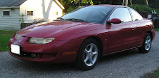
InternetAutoGuide, etc.) I came to the conclusion that my choices are extremely limited. As a matter of fact, I quickly narrowed my search to one vehicle. A Saturn SC1/SC2 from '95-'02 (the airbag years). A lightweight, plentiful, airbagged coupe available with ABS. Not only that, I decided there was a certain symmetry (or poetic justice) to converting a car from the same company that had a viable electric vehicle and decided to crush it.

AC/DC
So, what to put in this donor car? Most conversions use series-wound DC motors. They are simpler, cheaper, and have better low-end torque. However, they are also limited to low voltage, lack regenerative braking, are less efficient, and have limited RPM range. For me, the killer is the low voltage limitation. Low voltage means high current from the batteries, high enough that the only usable batteries are flooded Pb-Acid. By contrast, AC induction motors are more complex and expensive, but can use high-voltage battery packs, provide regenerative braking, are more efficient, have flatter torque curves, and can spin to ludicrous RPMs.

Since I've already decided that the electric components will outlast any donor vehicle (maybe 2 or 3 donors!) my assumption is that whatever system I use would last long enough to where I'd be able to take advantage of low-cost, durable lithium batteries that I believe will be available (eternal optimist that I am). The only way to take advantage of those next-generation batteries is to use AC. At this time, however, the best value in batteries are still flooded Pb-Acid so I'll start my EV life with those.

Will it work?
Requirements for the car:
  • Capable of highway speeds (though highway speeds kill the range)
  • Acceleration which is not embarassing (to a guy who drives a Civic)
  • Sufficient range to get me to work (15 miles @40 mph with less than 20% DOD
  • Cabin heat (New England weather)
There are a bunch of EV calculators on the web (Uve's, EVConvert, etc.), but they don't have information on AC motors/controllers. So I did a bit of my own modeling. I think it's good (my model matches the web calculators when I use DC motor parameters) but I must admit I don't know enough about how motors work to know for sure. But anyway, I think my component choice will give me the performance I need to make a viable commuter car.

My plan:
  • 156 V battery pack (12V flooded Pb-Acid batteries)
  • AC24 or AC24LS AC induction motor with DMOC445 controller
  • 220V on-board charger
  • Electric water heater for cabin heat
  • Power brakes (electric vacuum pump)
  • Manual steering, no A/C
My model predicts top speed of over 70 mph (though it might take the entire battery capacity to get there), 50+ mile range at 40 mph, and a battery lifetime of >4 years. Ok!

Budget
Hard to believe how much I'm going to be spending. There are cheaper ways to go (even sticking with AC), but I want to maximize my chances of success here so I'll rely on the experts at ElectroAuto and purchase one of their kits. Most likely the AC24 motor, but I may splurge for the extra torque of the AC24LS. So... gulp... $10K for a kit, another $2-3K for batteries, $1K for the donor, and probably another $500 in miscellany. I just have to keep in mind that it's cheaper than buying a new car, or even a late-model used one. And these components should last a lot longer.

So let's find a car!

Monday, March 30, 2009

Introduction

Welcome to my mid-life crisis. I hope it turns out to be a productive one.

Back in 2006 a co-worker of mine watched "Who Killed the Electric Car" and started talking up the concept of all-electric cars during lunchtimes. I vaguely remembered the EV1, but since I live far away from CA and AZ it didn't really enter my consciousness. But talking about it got several of us excited, and we thought we should start a company converting cars to electric and save the world! So I bought a book (Bob Brant's "Build Your Own Electric Vehicle") and started doing research. It seemed like a modestly-performing commuter car was technically and (almost) financially feasible. The trick would be convincing people that it's ok to deal with flooded Pb-Acid batteries and live with a constricted daily driving range for the privilege of bypassing gas stations for the rest of eternity. (Because who in the world can afford lithium batteries?) Fortunately one of us (not me) has a little business sense and convinced us that there was no money in it, so it would be at best an altruistic adventure. Ah well. Ok, scratch the "saving the world" part. But still...

Ever since then, I've had this notion in the back of my mind that even if it doesn't make business sense it would still be fun to convert a car. The company I work for has rolled out a "green initiative" and is offering an incentive for its employees to buy hybrid vehicles (via payroll rebate), so I asked if they would apply it to an all-electric conversion. They said yes, and also offered to allow me to charge at work. Beauty! So I decided to give it a go.

There are some very excellent blogs and websites chronicling the conversion of various cars. This will not be one of those. But by writing this I'll at least be recording my efforts to make the next conversion easier! (Just don't tell my wife there might be another!)